top of page

Construction
Methods
Chassis: The manufacturing process for chassis was a simple task. First off, the chassis needed to be plasma cut out of aluminum sheet metal. Once the chassis was cut out, it was taken to the machine shop where all the holes for other components were drilled out with the CNC machine and drill press. Grinders suited for aluminum material and files were also used to smooth and cut out rough edges.
Front bumper, Swing Arms, and Front/Rear Shock Towers:
To take the 2D solid works drawings and create the components, the process of using 3D printers were applied. The 3D printers were used in the MEC found in Samuelson, these printers used ABS and PLA material to print the components and were completed in a reasonable time for the time. Sanding down rough edges and drilling holes through support material were used to finish the detail work of the components.

Figure D.1 Drawing Tree

Figure D.1 shows the Construction for the Chassis. This picture is the process of drilling the holes on the flanges for the Swing arms to attach.
Figure D.2 Chassis Construction
Figure D.2 shows the rear swing arm construction. The swing arm was 3D printed at the MEC in Samuelson using PLA material. One the swing arm was complete two different diameter holes of .125 and .1825 inches needed to be drilled. The smaller hole is used to connect the shocks while the bigger hole is used to connect the transmission housing.

Figure D.3 Rear Swing Arm Construction
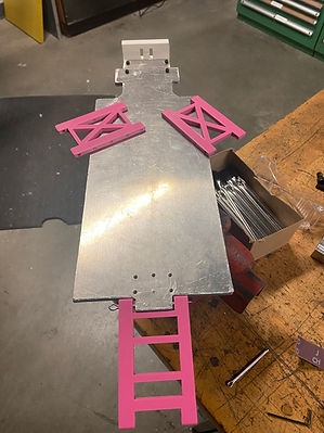

Both Figures D.3 and D.4 show the swing arm assembly that was completed and attached to the chassis. The swing arms were made using 3D printers from the MEC and Samuelson, these parts are made out of PLA material and are 100% infill. The swing arms fit snug on the chassis and are being connected to the chassis by cotter pints that provide a tight fit within all the hold diameters.
Figure D.4 Swing Arm Assembly
Figure D.5 Swing Arm Assembly Complete
Figure D.5 shows the construction of the rear shock tower. The rear shock tower was 3D printed used PLA material, once the print was complete it was up to the student do all the work such as hole drilling. The video shows the holes being drilled on the bottom of the shock tower that will connect to the chassis.
Figure D.6 Rear Shock Tower Construction

Figure D.6 Shows the construction of the front shock tower assembly. Due to size of the servo the team had to change the placement of the front shock tower that will still work with other components. This figure shows the placement of the front shock tower that was followed through with in comparison to the size of the servo.
Figure D.7 Front Shock Tower Placement

Figure D.8 Top View of Front Suspension

Figure D.9 Complete Assembly

Figure D.10 Rear Diff open view

Figure D.11 Top View of Rear Diff
bottom of page