top of page

ANALYSIS SUMMARY
All the analysis for the RC Baja car of the different components can be found in appendix A in the report. There will be many different methods of analysis that will be used to gain/determine design parameters of components that correspond with the set requirements. Some of the design parameters that will be gained from these analysis will be chassis thickness, shock tower hole size, swing arm design, etc. These parameters will then be used to help make drawings of the components found in appendix B in the report.
Engineering Merit
For the senior project there is a minimum of 12 analysis that need to be completed that shows some type of engineering merit. Examples of engineering merit areas that will be used for the 12 different analyses will include, statics, mechanic of materials, and physics. Free body diagrams from statics will be used to determine different loadings/forces and bending moments that will act on different components of the RC Baja car. Strength of materials will be used to analyze various stresses on components due to loadings and help determine material and thickness for the RC Baja car. Basic physics and kinematics equations can be used to analyze certain values such as impact force and energy needed to withstand a 1.5ft drop.
Analysis Images and Descriptions

Analysis#1 shows the impact force and energy needed to withstand when being dropped from a 1.5ft height. The 10lb force was used because in the requirements it was stated that car should not exceed more than 10lb, so this was used to determine the max force. The 10lbf was converted into kg and then used to find the force using F=ma, this found force will help determine the minimum thickness of the suspension arms. Figure A.1 also shows the energy absorption of the suspension. After the sum of the energy was found the value came out to be 14.9 ft-lb that suspension must withstand from a 1.5ft drop.
Figure A.1 Analysis #1
Analysis #2 shows the front impact force on the front of the car at 25 mph when driving into a wall. The 10lb force was used again in the analysis because in the requirements it was stated that the car should not exceed more than 10lb in weight, so this was used in the force equation once converted into mass. It can be assumed that it would take the car .1 seconds to go from 25mph to 0mph after contacting the wall. This time was used in finding the acceleration that was needed in F=ma equation. Once the mass and acceleration were found the equation was simple. The force on the front of the car came out to be 506.27N at a speed of 25 mph. This force will help determine the front bumpers design parameters which will be documented in the front bumpers drawing once completed in appendix B.


Figure A.2 Analysis #2
Analysis #3 shows the calculations for the minimum thickness of the chassis that would meet the requirement of the 120N force on the front end. The RC car was treated like a beam with a fixed end, there is a force in the middle of 44.48N which acts as the 10lb max weight of the car requirement and a 120N force on the front for front-end requirement. Shear and moment diagrams were done for the forces acting on the car, which would then lead into the bending stress equation to solve for the section modulus. For the bending stress, 48.72Nm was found from the moment diagrams and used for M and 240MPA was used for stress max since it is the yielding stress value for Aluminum Plate 6061 steel. Solving this equation gave the value of 203 X10-9 Nm3 for section modulus. From Appendix 1, the Section modulus equation is BH2/6 with H being the thickness for the chassis. Using this equation to solve for H, the analysis resulted in a design parameter of minimum required thickness of 2.8mm or .11 in. Since the minimum thickness is .11 inches it can be assumed that anything thicker should be acceptable, which is why the thickness for chassis will be .25 in. This thickness of .25 in seems more reasonable to work with when it’s time to machine the part because it might be hard to find raw stock of aluminum that is .11 in or close to that value.
Figure A.3 Analysis #3
Analysis #4 shows the calculations for the minimum arm length for the swing arms, this design parameter will help in meeting the requirement of the Chassis withstanding a 1.5N drop if landed up right. In the analysis a triangle was designed that represented the shock tower height, shock, length, and the unknown swing arm length. It can be assumed that the shock tower height will be 3in tall when created and the shocks will be 4in long. Laws of sines were used to the angle the shock should stand at when mounted, which was 33.33 degrees. Laws of sines was used again to find the unknown minimum length of the swing arm, which was 2.23 in. A design factor of 2 will be used to make the swing arm 4 in. By making the swing arms 4 in long it will allow the shocks to be moved up and down the swing arm depending on which position works the best with the shock.

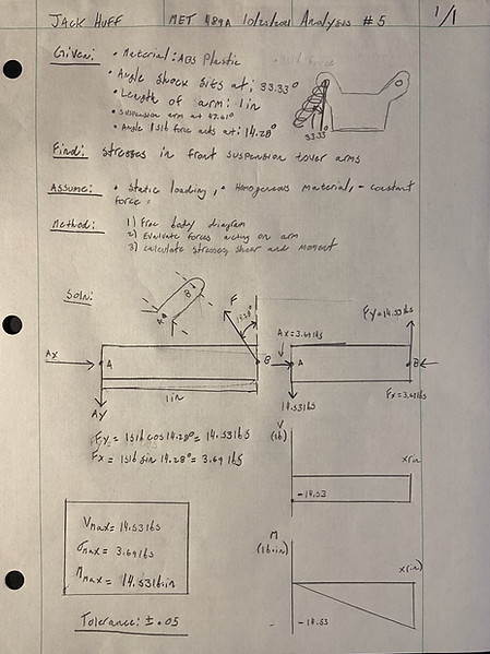
Figure A.4 Analysis #4
A problem the front shocks towers arm might experience during use can be fatigue due to constant force from the suspension struts. Figure A.5 shows the calculations for the stresses in the front shock tower arm, knowing these stress values will help in designing to meet the requirement of the front/rear suspension tower being able to withstand a 15lb force from the suspension strut. The benefit of designing for this requirement will be that the shock towers will not experience extreme fatigue from the assumed load. These stress values will also help find the minimum cross-sectional area that suspension tower arms should have in analysis #6. In the analysis, a free body diagram was made of the proposed suspension tower arm where the arm was treated like a beam. It can be assumed that the suspension strut will apply a force at at 14.28-degree angle since the suspension arm will sit at 47.61-degree angle and the shock itself will be at 33.33-degree angle, these values were found in analysis #4. Forces where then found in the x and y where Fy was 14.53lb. and Fx was 3.69lb. Shear and moment diagrams were then done to find shear max being 14.53 lb., normal stress max being 3.69 lb., and the moment being 14.53 lb *in since the arm length will be designed to be 1in. These stress values were found in this analysis and be used/documented in analysis #6 and in the DWG for the front suspension tower in appendix B-5.
Figure A.5 Analysis #5
The same problem and benefits of the design from analysis #5 can be applied to this analysis. Figure A.6 shows the calculations for the minimum cross-sectional area of the front suspension tower arms, this design parameter will help meet the requirement of the tower being able to withstand a 15lb force from the suspension strut. In the analysis the bending stress equation was used since one could find b and h in the moment of inertia equation, in this situation it can be assumed that the shock tower arms will be a square so b and h will be the same value. Once the equation is simplified down and set to solve for b, the moment value can be pulled from analysis #5 and plugged into the equation. The flexural strength for abs plastic is 11,000 psi, this value can be plugged into the denominator of the equation. Once the equation is solved, a b value of .2in is found. For the cross-sectional area design parameter, a standard size of .5in will be used for the base and height of the tower arm since this will apply a safety factor of 2.5. This parameter will be documented in the DWG for the front suspension tower in appendix B-5.


Figure A.6 Analysis #6
A problem that the rear shock can experience is that shocks will not be mounted at a good angle due to the height of the shock tower. Figure A.7 shows the calculations for the minimum height for the rear shock tower, this design parameter will help in meeting the requirement of the rear shock tower being able to hold the rear shocks at an angle between 30 and 60 degrees. The benefits of designing the rear shock tower this way is that it will give the shocks enough of an angle to be efficient in stabilizing the vehicle when in use. In the analysis a 30-60-90 triangle was created that represents the rear shock tower height, swing arm length, and shock length. The desired shock length side BC is to be 4 inches and the designed swing arm length AC is 4 in as well. Law of sines was applied to find the length BA which represented the rear shock tower height. After solving for BA, the design parameter of minimum rear shock tower height came out to be 2.3 inches. For simplicity, when making parts the same height of the front shock tower will be used which is 2.6 inches. This design parameter will be documented in the DWG for the rear suspension tower in appendix B-6.
Figure A.7 Analysis #7
Similar to the front shock towers, the rear shock towers will be exposed to fatigue due to the constant force applied by the suspension struts. Figure A.8 shows the calculations for the stresses found in the rear shock tower arm; these stresses are aimed at finding required values that will meet the requirement of the front/rear suspension tower being able to withstand against a 15lb force from the suspension strut. These stress values will also help find the minimum cross sectional are in the arms to withstand a 15lb force. The benefit of the designing the rear shock towers with this requirement is that it will minimize the amount of fatigue the shock tower will experience. In the analysis, a free body diagram was made of the proposed suspension tower arm where the arm was treated like a beam. The arm was designed to be 1.5 compared to the 1 in arms on the front tower since it will have to have more overhang on the rear to attach the shocks to the swing arms. Due to the requirement of the suspension arms on the rear having to sit at an angle of 30-60 degrees it will be assumed that the strut is causing a force at 30 degrees, which can be referenced in analysis #7. Forces were solved in the x and y where fy was 12.99lb and fx was 7.5lbs. Shear and moment diagrams were made with these values which ended up showing a shear max value of 12.99lb, normal stress value of 7.5lb, and a moment of 19.485lb in due to the 1.5 in arm length. These design parameters will be documented/used in analysis #9 which will help create a ASME Y14.5 drawing of the rear suspension tower documented in appendix B-6.


Figure A.9 Analysis #9
A problem that the RC Baja car might experience is not being able to withstand the force from the drop test. Figure A.10 shows the calculations to find the design parameter of a K value of the shocks needed to hold up against a 10lbf from 1.5 ft drop. This design parameter will help in meeting the requirement of the car being able to withstand a 1.5 ft drop. The benefit of designing the RC Car with strong shocks is that it will allow it to withstand all sorts of different drop heights. In the analysis, the equation 1/2kx^2=mgh was used to solve for the K value. Once the equation was simplified to solve for the K value, one could plug in 10lbs for m (analysis#1), 1.5ft for h since it is the desired drop height in the requirement, 2 in converted to feet for x since this is the assumed compressed length of the shock, and 32.2ft/s^2 for g. This equation will give a k value of 1076lbf/ft which would equate to 89.3lbf/in. Using this k value to plug into the force equation of f=kx, one can get a force rating value of 172.8lbf. This 172.8lbf is greater than the 10lbf from the drop making the shocks able to withstand the drop test. This design parameter will be documented in the DWG of the shocks in appendix B-8.

Figure A.11 Analysis #11
The same problems and benefits for analysis #11 can be applied to this analysis. Figure A.12 shows the analysis that checks to see if the design of the front bumper will hold up against the impact force. First, the bumper was broken into two parts where the first part of the bumper was analyzed. Forces in the x were solved for and found a normal force of 113.18lb from part 2 of the bumper, this makes sense since part one of the bumper will be having this same force applied to it on the front (equal and opposite reactions). Second, a moment of the back of the first part of the bumper was done to find a moment value of 198.065lb ** in. Lastly, a stress max equation was to find the maximum stress the bumper would experience compared to the yield stress of ABS plastic. The max stress came out to be 482.42 psi while the yield strength of ABS plastic was 10,700 psi. This comparison shows how the front bumper should be able to withstand the 506.72 N force from the impact test. This design parameter will be documented in the DWG for the front bumper in appendix B-7
Figure A.8 Analysis #8
The same problem and benefits of Analysis #8 can be applied to this analysis. Figure A.9 will show that analysis that calculates the minimum cross-sectional area of the rear suspension tower arms, this design parameter will help meet the requirement of the tower being able to withstand a 15lb force from the suspension strut. Like Analysis 6, the simplified bending stress equation can be applied because it allows to find b, which can serve as h as well since the shape of arms with be square. Once the bending stress equation is simplified, once can pull the moment for analysis 8 and the flexural strength of ABS plastic. Once this equation is solved with the known values, a minimum design parameter value of .22in is found for b and h of the arms. A value of .5 for the b and h will be used for the cross-sectional area of the arm because that is the same value of the front shock tower arms and will apply a safety factor of roughly 2. This design parameter will be documented in the DWG of the rear suspension tower in appendix B-6.

Figure A.10 Analysis #10
A problem that the front bumper may experience while in use is breakage due to the force from the impact test. Figure A.11 shows the calculations for the minimum Cross-sectional area that front bumper must have to withstand this force, this design parameter will help in meeting the requirement of the front bumper surviving the 506.27N force from the impact test. The benefits of designing the front bumper this way is that it will protect the chassis and the entire of the car from strong forces on the front end. In the analysis, the area was found by using the stress = force/area equation. The force was already known from analysis #2, which was 506.72N or 116.81lbf. The yield stress of ABS plastic was 10,700 psi, so these values allowed the student to simplify the equation for a cross sectional area and find a value of .0106in^2. Next, from appendix one in Mott the area for a square is A=H^2 which allowed the student to find a h value of .1029in. The minimum cross-sectional area will be .0106in^2, however the student will use values of .5 for the base and height to machine easier and give a safety factor of roughly 5. This design parameter will be documented in the DWG for the front bumper in appendix B-7.

Figure A.12 Analysis #12
bottom of page